This is part 2 of the series. Read part 1 here: https://nadejde.com/2021/01/27/building-sticker-1-planning/
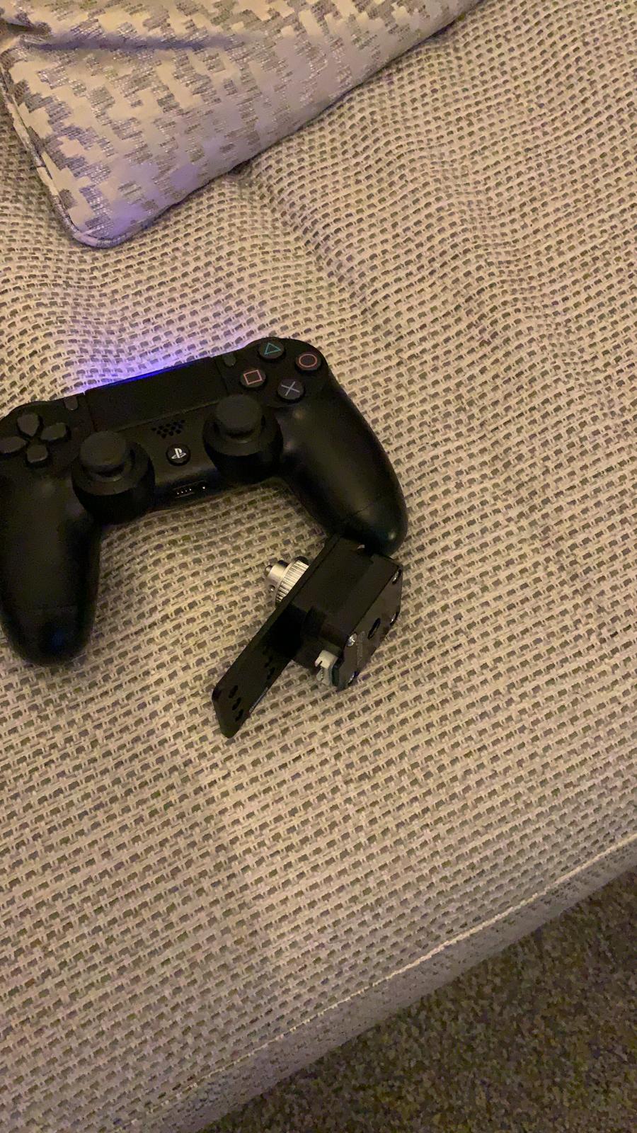
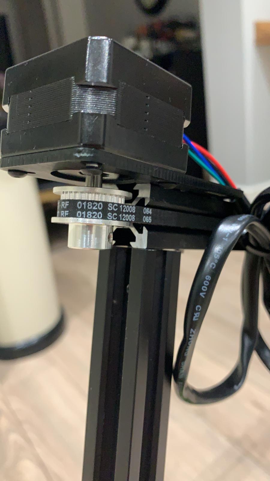
So as I mentioned in the last blog I ended up buying kits following openbuilds specifications from ooznest. This is how they get delivred and some photos my friend Marius took while assembling the kit. Thanks for your help!


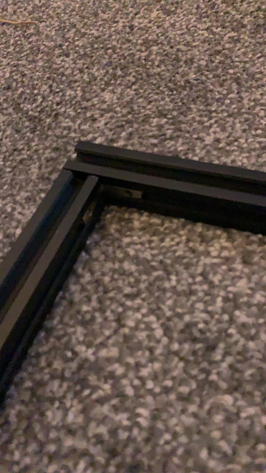
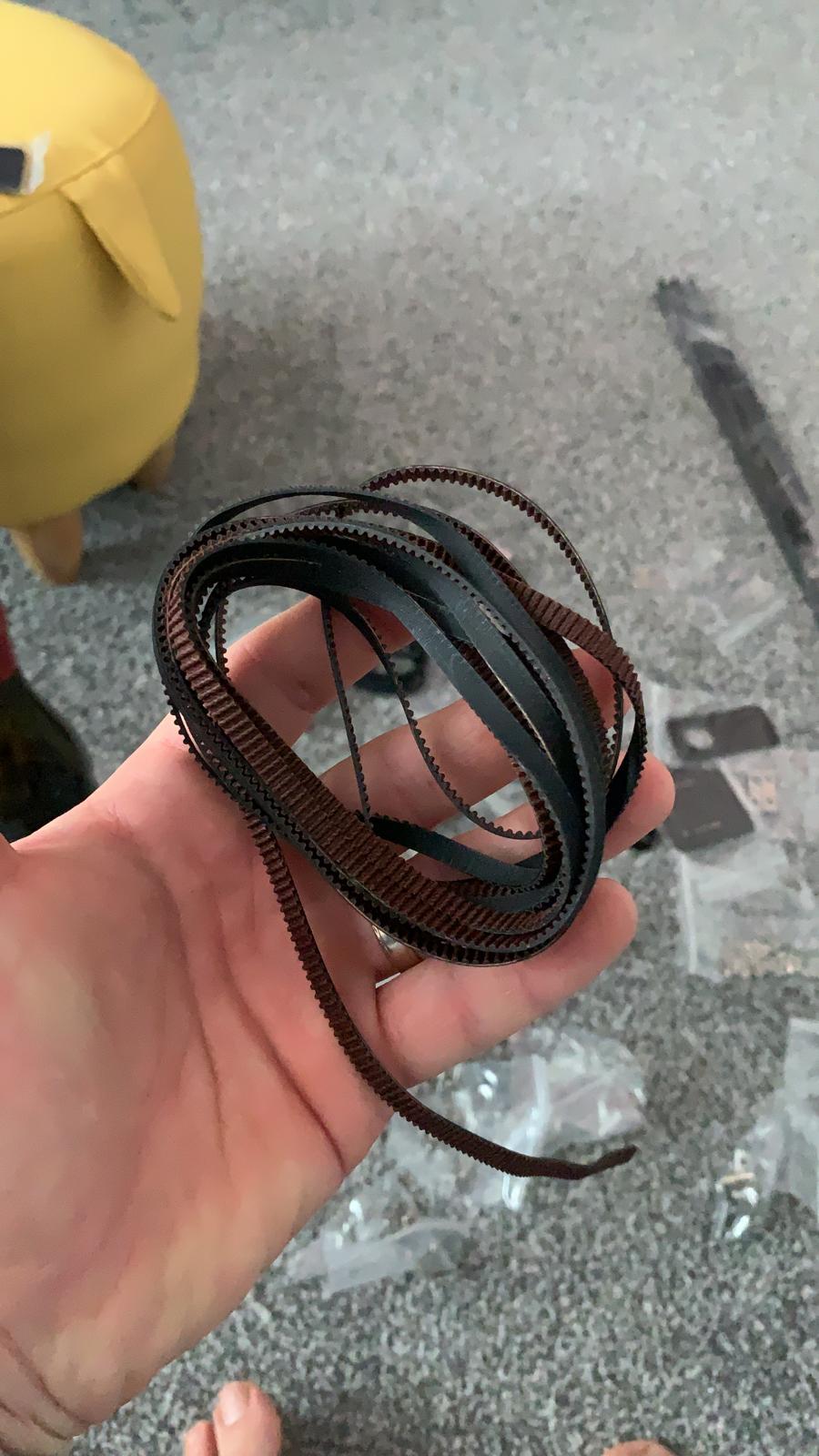
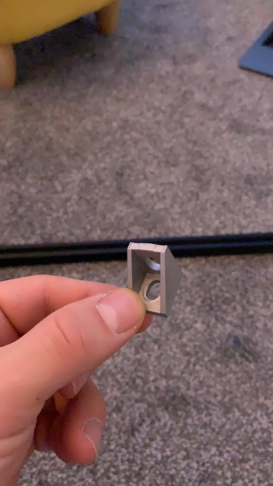

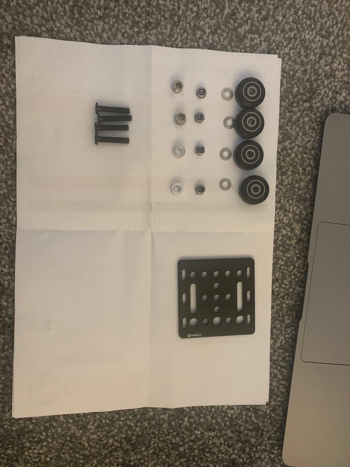


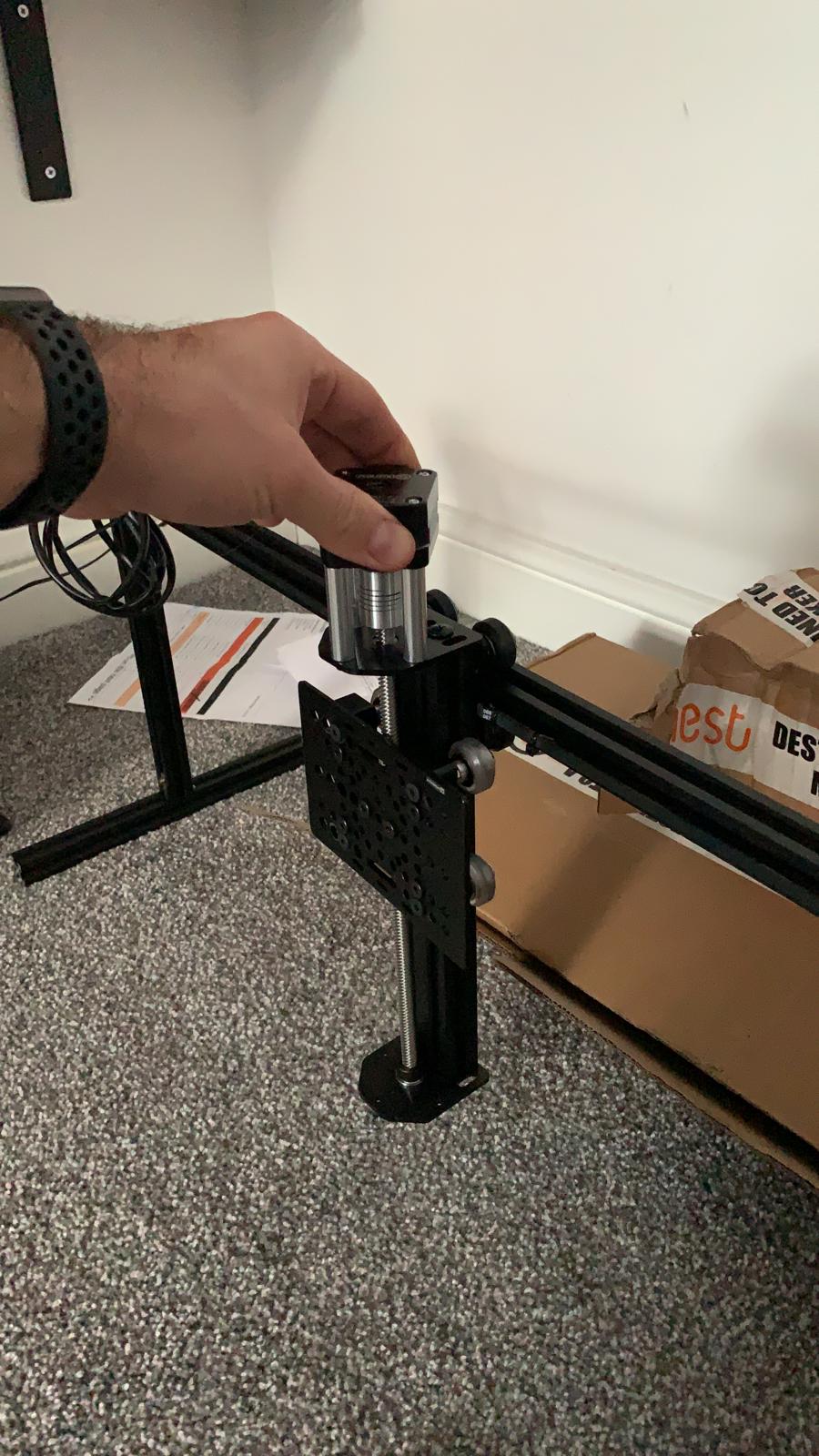

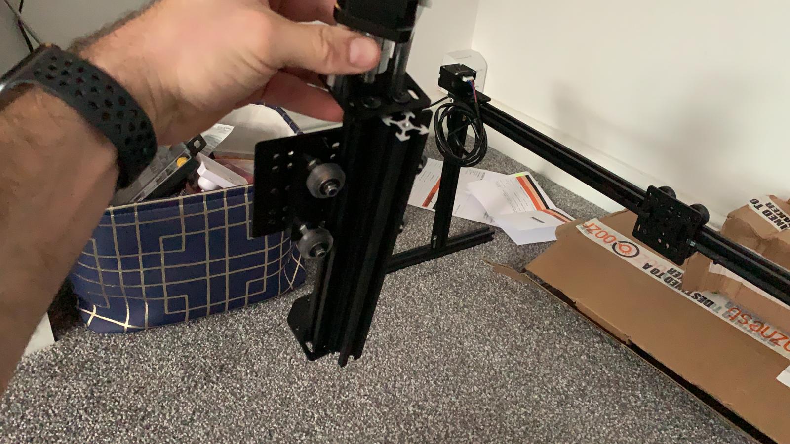
Building it together was straightforward by following the guid on youtube (so I’ve been told as I’ve not done it myself:p)
The next piece of the puzzle was controlling the motors to move the carriage left right and up and down. As I’ve mentioned before I decided to use a raspberryPI to control the whole thing. I chose raspberryPI because it is very flexible and in case I drop the project at some point I can still use it for lots of other things. The way you control electronic components with the raspberryPI is through its GPIO ports https://www.raspberrypi.org/documentation/usage/gpio/. It is a very basic way of turning current on or off through a single circuit by writing a simple piece of code. You can even do it in Scratch! for small children to play with:) https://projects.raspberrypi.org/en
# example code for turning LED on through python
# https://gpiozero.readthedocs.io/en/stable/recipes.html#pin-numbering
from gpiozero import LED

led = LED(25) # using GPIO port number 25
led.on() # sends electric current through GPIO port 25
led.off() # stops sending electric current through GPIO port 25
The raspberryPI can’t control the stepper motors on it’s own directly. A normal DC motor you would just give it the required power and it would spin. The stepper motors however need a more complex input that you can provide through a controller chip. Now I had the smallest type of NEMA17 motor:
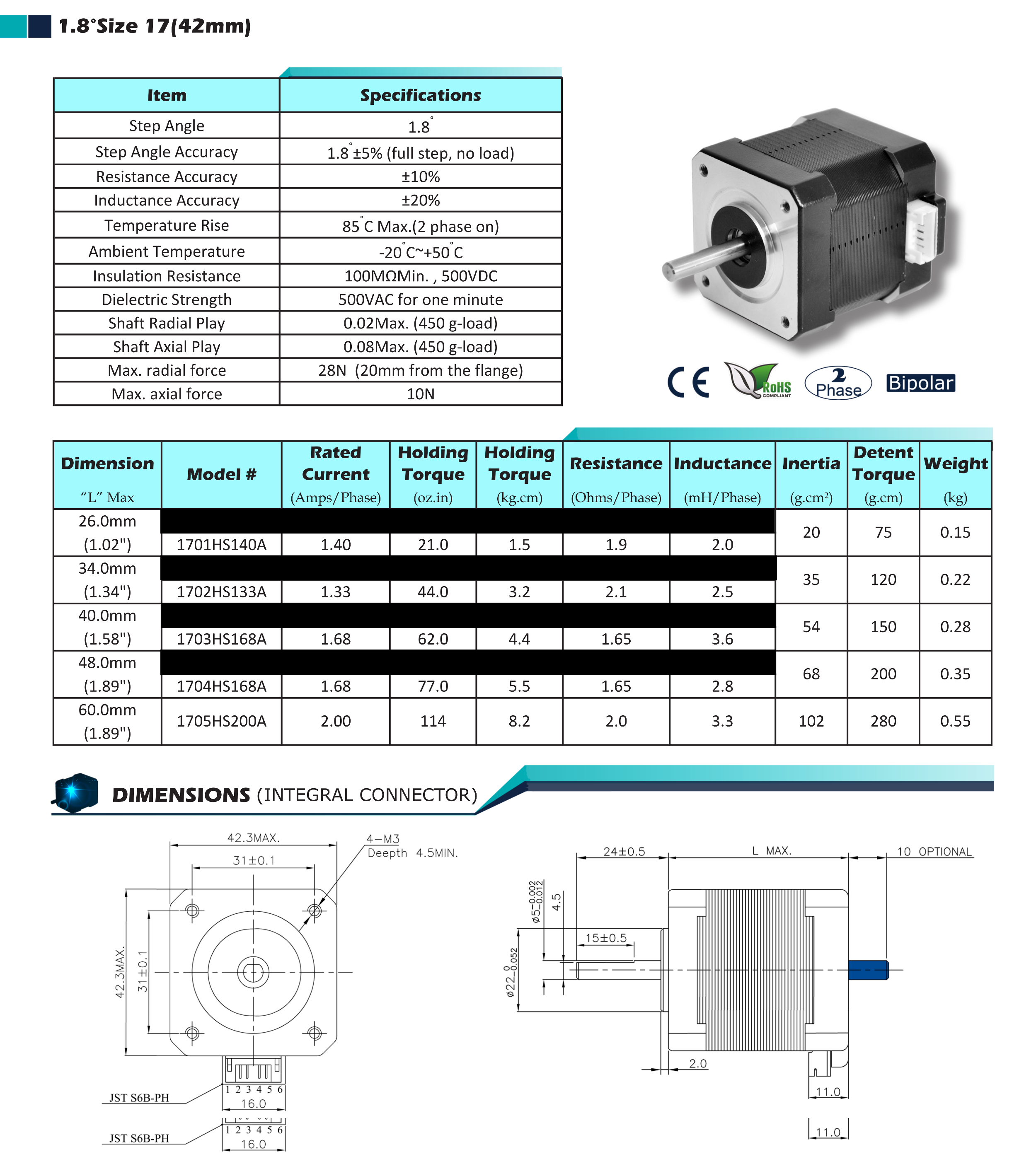
Key things to note are that it works at 12-24V. Also important are the Rated Current values 1.4Amps/Phase and the Internal Resistance of 1.9 Ohms/Phase which will come in later. At this point I was not really aware of how all these things matter. I just look at the 12-24V and 1.4Amps rated current when deciding what controller to use. With Vitaliys help I decided to get a HAT for my rapsberryPI: https://thepihut.com/products/stepper-motor-hat-for-raspberry-pi
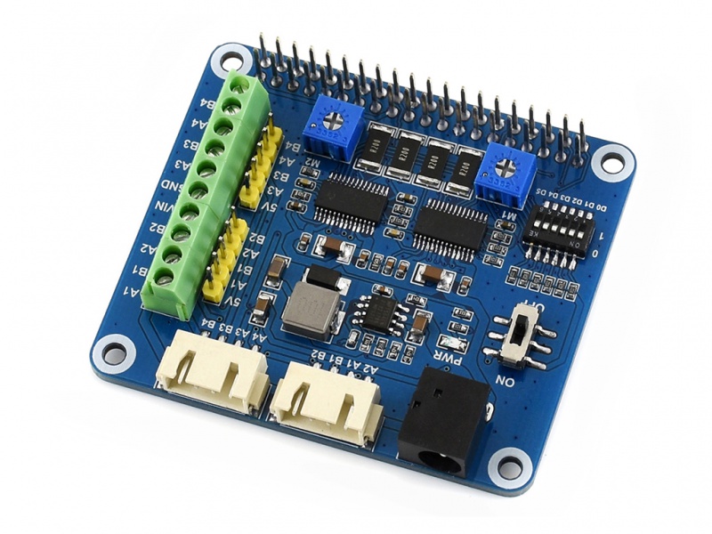

The hat sits on top of the raspberry board and is controlled through the GPIO ports. This one can control motors with up to 24V and can output 2.5Amps so everything looked good on paper. I even managed to control a motor very quickly with it. I didn’t like the code though and the documentation as it was poorly translated from Chinese https://www.waveshare.com/wiki/Stepper_Motor_HAT. I also didn’t like the fact that it uses alot of GPIO ports to control the two motors. In my grandiose plans of controlling tens of robots from the same raspberry PI this would have been a problem:) . This is the example code:
Motor1 = DRV8825(dir_pin=13, step_pin=19, enable_pin=12, mode_pins=(16, 17, 20))
# 6 pins are used up already for 1 motor!
Motor1.SetMicroStep('softward','fullstep')

Motor1.TurnStep(Dir='forward', steps=200, stepdelay = 0.005)

time.sleep(0.5)

Motor1.TurnStep(Dir='backward', steps=400, stepdelay = 0.005)

Motor1.Stop()
After tinkering with this hat for a while I decided to try a different one also to see if would be easier to work with. I went for the adafruit hat: https://thepihut.com/products/adafruit-dc-stepper-motor-hat-for-raspberry-pi-mini-kit. On paper this again sounded quite good for what I needed. It can do 12V at 1.2Amps with a peak of 3Amps. With my understanding of electronics that sounded like it could to the trick fine. It also involved some light soldering which I was happy to do!
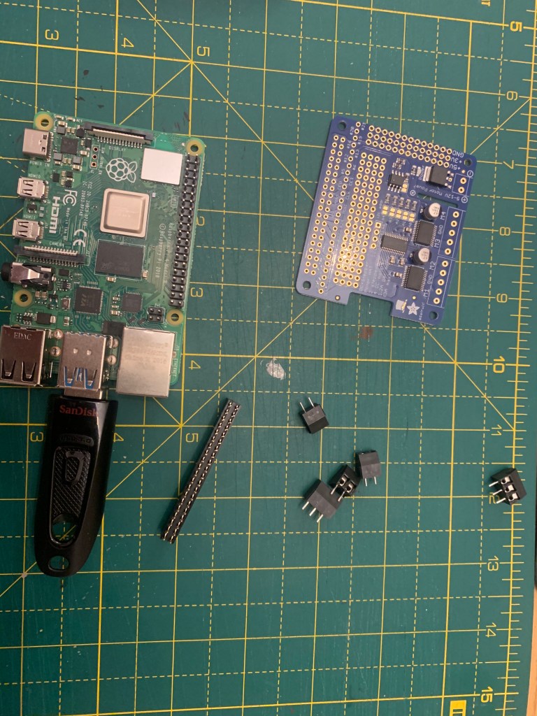


This HAT also has the advantage that it only uses two ports on the raspberry and you can have multiple HATs stacked one on top of the other and use them together. I2C standard: https://learn.adafruit.com/adafruits-raspberry-pi-lesson-4-gpio-setup/configuring-i2c. In my grand plans this was good:)
from adafruit_motorkit import MotorKit
from adafruit_motor import stepper

kit = MotorKit(i2c=board.I2C())
for i in range(0,100): # move a 100 steps
  kit.stepper1.onestep(direction=stepper.BACKWARD, style=stepper.DOUBLE)
kit.stepper1.release()
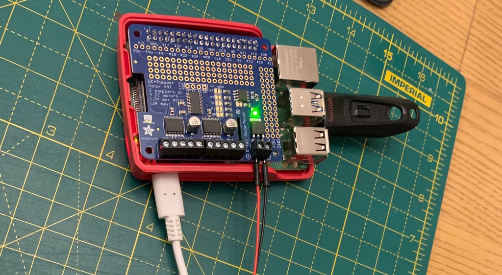
After plugging everything together and writing the simple code I tried to plug in the motor and let it drive it but it wasn’t doing anything and there were lights blinking on the board. I ended up asking on the adafruit forums and someone kindly explained to me how Ohms law applies and why the adafruit board was not good for the motors I needed to drive: https://forums.adafruit.com/viewtopic.php?f=8&t=173540&p=846120#p846120. Ohm’s Law: I = V/R. So the peak current draw will be 12v / 1.9 Ohms = 6.31A. In other words, these motors are not compatible with the HAT. But wait! the technical specification said 1.4!!! A bit more learning and as it turns out it would eventually go down to 1.4Amps once the internal fields stabilise but as it powers up it will probably try to draw 6.4A at peak if you don’t limit the current somehow. Luckily the Waveshare hat can do that! It has the current chopper and you can actually set it to not go above a certain value so it turns out the initial board was the better one for the job:)
I went back to that board and reconnected all the motors and also used a multimeter to test the Amps used during normal motor movement. It works great on the waveshare hat and you can see it really does use 1.4Amps under normal operation:
Hazaaa!! So now we can move the motors! Next step is to try and move it to the correct place. In order to do that we need to translate steps into distance. I found this little video that explains things in theory: https://youtu.be/6vY26CIrVwg. That didn’t work for me exactly like expected but the steps are the same. One of my motors does a full rotation in 200 steps. Because of the pulley used is 30 tooth 2mm gap one full rotation is in theory 60mm / 6cm. However in reality it turns out depending on how you send the commands to the motor and the various errors you won’t get this ideal distance. I struggle with this a bit as I was expecting the error to be bigger on longer distances and smaller on shorted distances. I did some tests:
    @0.0007 step delay
    2666 steps = 810 mm = 3.2915 steps/mm
    2500 steps = 760 mm = 3.2894 steps/mm
    2000 steps = 615 mm = 3.2520 steps/mm
    1500 steps = 462 mm = 3.2467 steps/mm
    1000 steps = 315 mm = 3.1746 steps/mm
    500 steps = 160 mm = 3.1250 steps/mm
    200 steps = 70 mm = 2.8570 steps/mm
    100 steps = 39 mm = 2.5641 steps/mm

    @0.0005 step delay
    2666 steps = 817 mm = 3.2631 steps/mm
    2500 steps = 767 mm = 3.2594 steps/mm
    2000 steps = 617 mm = 3.2414 steps/mm
    1500 steps = 470 mm = 3.1914 steps/mm
    1000 steps = 320 mm = 3.1250 steps/mm
    500 steps = 166 mm = 3.0120 steps/mm
    200 steps = 80 mm = 2.5000 steps/mm
    100 steps = 46 mm = 2.1700 steps/mm

    theoretical
    200 steps = 60 mm = 3.3333 steps/mm
After the tests I realised a few things:
- Using different step delays yields different errors. Step delay is the pause you have between two step commands. The way you control the stepper is step by step and there needs to be a break between each command. It seems that with shorter delays the errors are larger and the motor overshoots. From the theoretical values for example at 2666 I was expecting 800mm movement. At 0.0005 step delay I was overshooting by 17 mm. At 0.0007 step delay I was overshooting only 10mm.
- The distance it overshoots seems to be more or lest constant for longer distances and is at 17mm when using the 0.0005 step delay. This means its easy to correct this by just removing a fixed number of steps from each move command.
- On very short distances it overshoots by more than on long distances. This is more prominent when using the 0.0005 step delay (the short one). This is why I ended up using a longer step delay for moving shorter distances and the shorter one for longer distances.
- The movement is not 100% precise. If I do the same number of steps 10 times its not going to always stop in the same place. This is actually a bit disappointing as one of the selling points of stepper motors is that they are very precise!
- I had to add physical stopper at both ends to correct the errors that accumulate over time. Every time I move it to one end or the other I overshoot it a little bit but the stopper forces it to be on the exact starting/ending position.
I’m still not really sure where the problem is causing these errors. I would not expect the step delay to cause this much of a difference. It might be that the controller board is not able to output enough current at the start or perhaps even the board is not the best:) For now I got it into a place where I can reliably move it to where I want most of the time so I am happy. You can see it at work again here:
For now all of this works as I’m just building a prototype but at some point I will want to go back and try a rebuild with a better controller and bigger motors. I’m looking at this bad boy which can power 4 motors at the same time: https://thepihut.com/products/tinyg-cnc-controller-board-v8
Stay tuned for my next post on the sensors and card grabbing mechanism!
